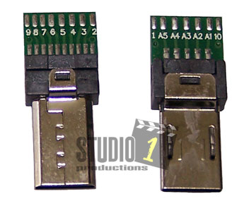
Pin Out Chart for the Sony Multiport Connector or the Sony Multi
Terminal Connector
The pin out chart is for
the way we have our Sony Multiport Connector labeled. The
information below came from Sony and other sources and it is accurate to
the best of our knowledge. This information if for Sony camcorders
and Sony cameras from 2014 to today. Please Note: The
2013 Sony Camcorders had the Multiport or Multi Terminal
connection, but it may not be wired as listed below.
| Pin |
Usage |
| A1 |
VBUS (5 volt, max 2A) |
| A2 |
USB D-1 |
| A3 |
USB D+1 |
| A4 |
USB ID |
| A5 |
Ground |
| |
|
| 1 |
Power On / Off - Short to Ground to toggle between Power On or Off. |
| 2 |
Ground |
| 3 |
Composite Video Out - Not supported when using a
wired remote control unit |
| 4 |
Audio Out L / Shutter Release
- Shutter with direct trigger cable. Note: Audio is not
supported when using a wired remote control unit |
| 5 |
Audio Out R Audio / Activate Camera / Focus
- Focus with direct trigger cable. Note: Audio is not supported
when using a wired remote control unit |
| 6 |
Select - resistor to detect the connected cable or accessory type. Resistor to Pin 2
or Pin 10 depending on accessory type or cable. Use 100K ohm Resistor. |
| 7 |
UART RX / Boot Serial In - optional input for serial interface (debug) and boot loader. No Boot Loader. |
| 8 |
UART TX / LANC Sig - optional output for serial LANC
interface for debug / No LANC control |
| 9 |
XReset Req / Input for reset request |
| 10 |
2.8 volt to 3.3 volt output |
Not all functions may be provided by all camera/camcorder models.
You can NOT control the camera with a wired remote control while providing video/audio output using the Multi
USB terminal. You have to use the HDMI output when you are connected to a wired remote control. This is just the way Sony has
designed the multiport or multi terminal to work.
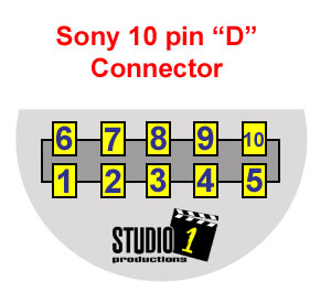
Sony 10 pin "D" Connector Pinout
| Pin |
Usage |
| 1 |
Audio Out - Left Audio |
| 2 |
LANC Data Signal - (Tip on 2.5mm plug) |
| 3 |
Ground -
(Sleeve on 2.5mm plug) / S-Video Ground (Pins 1 & 2 on S-Video Connector) |
| 4 |
+5 Volts - (Ring on 2.5mm plug) |
| 5 |
S-Video Chroma Signal (Pin 4 on the S-Video Connector) |
| 6 |
Audio Out
- Right Audio |
| 7 |
LANC Select - Must connect pin 7 to 8 with 100k ohm resister |
| 8 |
Ground |
| 9 |
Composite
Video Out |
| 10 |
S-Video Luminance Signal (Pin 3 on the S-Video Connector) |
NOTE: Sony uses a LANC select signal. This tells the camera that a LANC controller is connected. You MUST connect pins 7 and 8
together using a 100k ohm resistor if you are connecting a LANC controller to the camera. Otherwise, the LANC will not be
functional.
Not all functions may be provided by all camera/camcorder models.
We do NOT sell the Sony 10 pin D Connector.
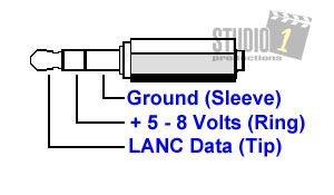
Sony LANC Pinout
Canon LANC Pinout
| Pin |
Usage |
| 1 |
LANC Data - (Tip on the 2.5mm Plug) |
| 2 |
+5 Volts
- This powers the LANC controller (Ring on 2.5mm
Plug) |
| 3 |
Ground - (Sleeve on 2.5mm Plug) |